Theme: "Hand Anatomy"
Introduction
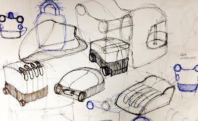
This week our design team focused on refining our current glove concept. The main objectives for this week was to begin creating a style and types of materials and to link the glove and the corresponding notification system. Other proprieties included developing the features and technologies which will be integrated into the glove such as flex sensors, grip pads, breathing tabs and an accelerometer.
Research
In
order to understand more about the different types of grips and how the anatomy of the human
hand plays a significant role, I decided to research tennis grips. Cooper
(2012) states a popular and adequate point of reference on the hand is the space between the thumb and index finger. The image below shows the space between the two regions and how they intersect with the palm of the hand.
Tennis players prefer to use the base knuckle of the index finger as its position corresponds to the center of the palm. Due to the fact that people are use to sensing the direction that their palm is facing, the palm is able to intuitively sense the direction the racquet is facing. The diagram below details the 'V' space on the hand which is essentially the base knuckle of the index finger and whats known as the 'Heal-pad' which is the region directly opposite the thumb and below little finger.

This information has proved to be highly beneficial to this semester's project as it outlines important regions on the hand in relation to grip and performance. The most significant aspect of this research explains the versatility of a tennis racquet's grip and how it allows players to constantly adjust to the situation. Similar to our project, it is important for the design team to understand exactly where to place the grip pads which will provide the user with a full range of motion, improved comfort and a great deal of versatility to use numerous types of tools and equipment. Given the fact that the user group is constantly using different types of tools both large and small, the user requires a glove that can adapt and provide the best performance for each situation. As a result, the placement of the grip pads must address specific areas on the hand that will benefit the user's control and ability.
The fact that tennis players are continually using a variety of different strokes including backhand, forehand and volleys, it is the responsibility of the grip to provide the player with multiple options to adjust quickly and ensure correct technique. Therefore, on the basis of this research, I believe our team should employ the same principles used to design tennis grips.
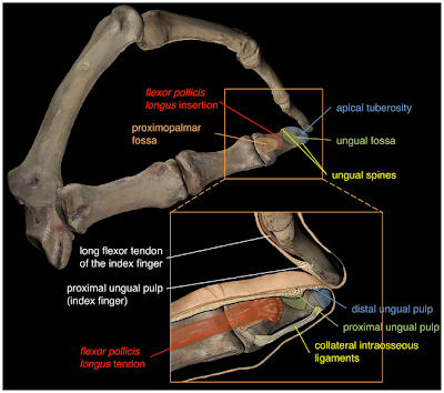
In terms of anatomy of the human hand, there are no muscles inside the fingers. In fact the muscles which control the finger joints are located in the palm and the mid forearm. These muscles are connected to the finger bones by tendons which control the movement of the fingers. After prolonged use of heavy equipment the user will begin to experience pain and discomfort as a result of muscles in the palm and mid forearm become fatigued and sore. Thus, the glove will need to place grip pads according to areas of the palm that provide the most power generation and control of the fingers to maintain comfort and reduce pain.
In total, there are ten muscles that make up your hand grip. Three of these muscles are located in the forearms and wrists and the other seven are located in the hands themselves (AthleticQuickness, 2012).
The image above indicates the locations of varies superficial hand grip muscles of the left hand.

The image above details the locations of the deep hand grip muscles of the left hand.
In addition, I have done further research into specific muscle groups that provide different types of support and control to the thumbs and fingers in order to identify the best possible locations for grip pads. The three muscle groups included in this video are Adductor Pollicis, Abductor Pollicis Brevis and Abductor Digiti Minimi (hand).
The adductor pollicis muscle is considered a forearm muscle and is involved in the movement of the hand and fingers. However, its specific function is to adduct the thumb's carpometacarpal joint.
The abductor digiti minimi (hand) muscle is a particularly strong skeletal muscle and its main function is to pull the little finger away from the other fingers. This process is known as abduction. The muscle plays an integral role when the hand grasps an object tightly as it helps to flex the metacarpophalangeal joint.
The main function of the abductor pollicis brevis is to abduct the thumb, or move it away from the palm. This muscle is also involved in the extension as well as opposition of the thumb.
These three muscle groups will play a significant role in regards to where each grip pad will be located on the hand.
Hand Sweating
There are two types of sweat glands in the human body,they are the Eccrine sweat glands and the Apocrine sweat glands. The sweat glands which I will focus on for the purpose of this design project are the Eccrine sweat glands. Humans utilize Eccrine sweat glands as a primary form of cooling and body temperature regulation. These glands cover the majority of the body, but are highly concentrated on the hands, feet and forehead. More importantly, this type of sweat is clear and odorless as it is mostly comprise of water and salt.Below is an image of the Eccrine sweat glands.
Design Solutions
Based on this research I have developed my own concepts relating to sweat glands and different type of grip.
Firstly, I decided to look into where I would place breathing pads to provide the user to improve the palm's ability to breath and perspire effectively. The hand silhouettes below detail exactly where the breathing tabs will be located. The idea behind the positioning of these tabs is based on research. The back of the hand has four slight raised breathing tabs underneath each knuckle. These tabs are raised so when the user grasps a tool they will be automatically compressed and therefore draw out the moisture in the hand and allow the palms to stay cool and dry. The perspiration will be squeezed out through the tabs located on the top of the hand. Breathing tabs are also located around each finger as much friction and movement is associated with these regions and as such will generate heat. In addition, I sort to address the issue of blisters and calluses by making the material on the back side and top of the hand see-through to allow the user to monitor the development of any blisters or bruising.

In terms of grip pad placement, the image below illustrates where grips will be place. Again, the justification for their positioning is based on human anatomy research and tennis grips.
The placement of the grip pads have been located according to specific muscle groups and their functionality, common regions used to grasp objects and surface areas with the optimine strength and control performance. Furthermore, the entire underside of the thumb has been incorporated with a grip due to the thumb's prehensile nature. John Napier proposed two primary prehensile grips: the precision grip and the power grip. The power grip is when the fingers clamp down on an object and the thumb makes a counter pressure. The precision grip is when the fingertips and thumb press against each other. The image below is an example of a precision grip. Based on this, a grip has be positioned on the index finger to help provide additional support as well as versatility for the user.
One example of a precision grip is opening a jar only with your fingertips. This information highlights the need to place grips along the fingertips to provide the user with extended capabilities while grasping complex tools. The image below details these specifics.
References: APA
Cooper, J. (2012). Simple Guide to Forehand Grips: Planes of the Racquet Handle. Retrieved from
http://tennis.about.com/od/forehandbackhand/a/simplefhgrips.htm
AthleticQuickness. (2012). Sports Anatomy Lesson: Hand Grip and Wrist Muscles. Retrieved from
http://www.athleticquickness.com/page.asp?page_id=102


_Page_01.jpg)
_Page_02.jpg)
_Page_04.jpg)
_Page_05.jpg)
_Page_06.jpg)
_Page_10.jpg)
_Page_11.jpg)
_Page_12.jpg)
_Page_14.jpg)
_Page_15.jpg)
_Page_16.jpg)
_Page_18.jpg)


